Things to consider before BUYING the kit
- Is your radiator core support STRAIGHT? If not, get that fixed first. Details below for why
- Are you using a non-SVO T-3? Like from an xr4ti, RS TURBO or GT TURBO? Consider upgrading to an SVO cold side or a new turbo first. Details below for why
I started with a non-intercooled T-3 turbo from an XR4Ti. How do you know it’s from a non-intercooled car? It has two bolt holes on the cold side output and ‘ears’ instead of just the circular output like the SVOs.
I started with a bent radiator core support. I didn’t have the A/C re-installed yet, so it wasn’t obvious how badly bent the core support was. Since the front end of the car was replaced to repair all the rust years ago, I don’t know any history on why it’s bent, but I suspect someone put a rope or chain on it to pull or tow the car.
Why is this a big deal? The intercooler needs to go between the fog light bar and the radiator support. If the radiator support is pushing out, it won’t be able to sit parallel to the radiator.
Since the Capri is a dark color I don’t have a good picture showing how bent it is, but take my advice and get this straight!
Installation Steps
1) Jack up the car, front and rear and use jack stands. Many people just do the front, but I found being level helped a few times as I tried to get the intercooler aligned.
2) Disconnect the battery. The number of times I bumped the battery doing this made me glad I did this!
3) Remove both wheels. They just get in the way.
4) Remove the inner wheel liners. I didn’t do this and in hindsight I should have. Some of the fitment issues I had early on was because the liner was pushing on the tubing. I eventually cut around where it needed to be, but not having the liners makes it much easier. Plus it will give you more light when you’re trying to adjust everything.
4a) remove the charcoal canister. It is in the way. I still need to figure out where to put it back. For now the line from the gas tank is behind the headlight but I don’t like that.
5) As mentioned, I don’t have A/C but you need to remove the brackets that hold the A/C condenser. I’ve read several places that you can push/pull the condenser closer to the radiator without the brackets to give you more room.
6) Find the center of the radiator opening. I put a piece of painter’s tape on the core support and marked it on there.
7) Find the center of the intercooler. Same idea, use tape to write on where the center is.
Some people also said their intercooler input/output were offset from center. Mine were on center, but check now. It might be a valuable piece of information as you’re trying to fit all the pipes in case you need to flip it.
8) Now using jack stands, pieces of wood and wood shims center the intercooler and push it as far up as you can into the gap between the bumper and the radiator support and center it using the tape marks. At a minimum it should be flush with the bottom of the core support.
At this point you may say ‘but I see all these pictures of people when their's hanging down a couple of inches below the core support. Me too. But that is very wrong. Not sure how it worked for them but it didn’t for me and exchanging emails with Stinger’s tech support they said to get it up as high as you can.
9) Now look at the input/output tubes to the intercooler and install the silicon hoses and clamps. You can tighten the clamp to the intercooler down tight now, but leave the other side loose. Ideally these should be right below the bumper mounts. If not raise the intercooler higher. This is one of the first areas where you have some adjustment room.
10) Another issue at this point is the power steering cooler. If you car came with one, you may need to bend it out of the way or unbolt it and slide it around so the outlet clears it. I had to remove mine (though the 1984 RS Turbo didn’t come with one from everything I can find out). Remember the bent core support? It was really bad where the cooler came through so I had to remove it. No amount of bending would get it out of the way of the intercooler outlet.
11) Now start installing the tubes from the throttle body to the driver’s side of the intercooler. I found using a strap to hold the tube until you got the one attached to the intercooler on saved me from cursing a lot. Keep the clamps loose, but tight enough it takes some effort to adjust the pipe. Too loose and it will fall apart, too tight you won’t be able to adjust.
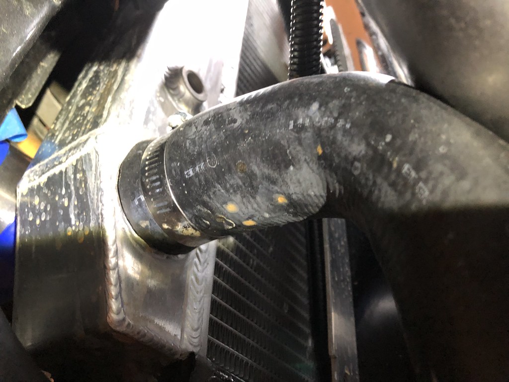
Now for the first issue I ran into. The ‘U’ pipe from the intercooler to the throttle body pipe sits on the lower radiator hose. Stinger support says this is okay, but I also saw some pictures/advice of people trimming the lower hose an inch. I did not.

12) Now check for clearance against the fan. Since I wasn’t running a stock fan or stock radiator I had to tweak the ‘U’ piece of the piping on the driver’s side to get as much clearance as I could. I played with how far the pipe was into the intercooler (the silicon gives you the ability to push into almost into the intercooler, or pull it out almost an inch. Mine worked pushed against the intercooler.

13) Clocking the turbo. Now the cursing really started. Since the engine and turbo came from an xr4ti, there was not a top mount intercooler like the SVOs came with. So I went online and bought a 90 degree elbow instead of cutting the ‘ears’ off the turbo.
Here is what I TRIED. This didn’t work but I want to show you want I’m talking about with the elbow and ‘ears’.

The first step in clocking the turbo is to loosen, but not remove the bolts holding the cold side (output to the throttle body side) so you can rotate the housing so the outlet is straight up, or more ideally slightly angled towards the strut tower.
Of course the loosened bolts hit the oil return, or the wastegate actuator hits the oil return. I was scratching my head at this point and went online to look at pictures of other installs. And guess what? EVERY one I found was an SVO cold side. Turns out that the bolt placement on the cold side is DIFFERENT between SVO and non-SVO turbos. And no matter how you try to position the cold side with the ‘ears’ turbo you either hit the drain line or can’t get the angle on the pipe from the intercooler you need. In the above picture the actuator had been removed to just SEE if it was possible.
The issue is where the bolts are on the cold side is basic math. T-3 turbos have 6 bolts holding 3 pieces of metal around the edge of the cold side. Loosen them and move the cold side orientation. The wastegate actuator is attached on one of those pieces of metal. So you have only 6 places to put it, and no wiggle room that doesn’t alter where the output lines up. Turns out the position of these bolt holes on the SVO turbo allows easy attachment of the actuator with the output rotated towards the strut tower, but the non-SVO puts the actuator right where the oil drain wants to be. I don’t have a picture but it is clear the SVO bolt holes are spaced differently around the cold side when you line up the outlets.
14) At this point I did something kind of dumb/kind of motorhead. I decided, well, time to upgrade the turbo. I built the engine for much more airflow, maybe this issue with the turbo fitting is the trigger to buy a new turbo. (Yes my wife just shook her head when I told her this.)
There is a whole other blog post about that experience, but let’s say 3 months later I bought a real Garrett T3/T4 Stage III hybrid and was able to clock it correctly. Still had issues with the wastegate actuator, but it was an easier fix than the stock T-3 would have been.
Teaser

15) Now that I have the turbo where I want it, I started again on the passenger side piping. First problem I encountered was the pipe from the turbo to the ‘U’ hit the top radiator hose. Unlike the bottom there was a LOT of interference so I had to trim the hose about 2 inches.
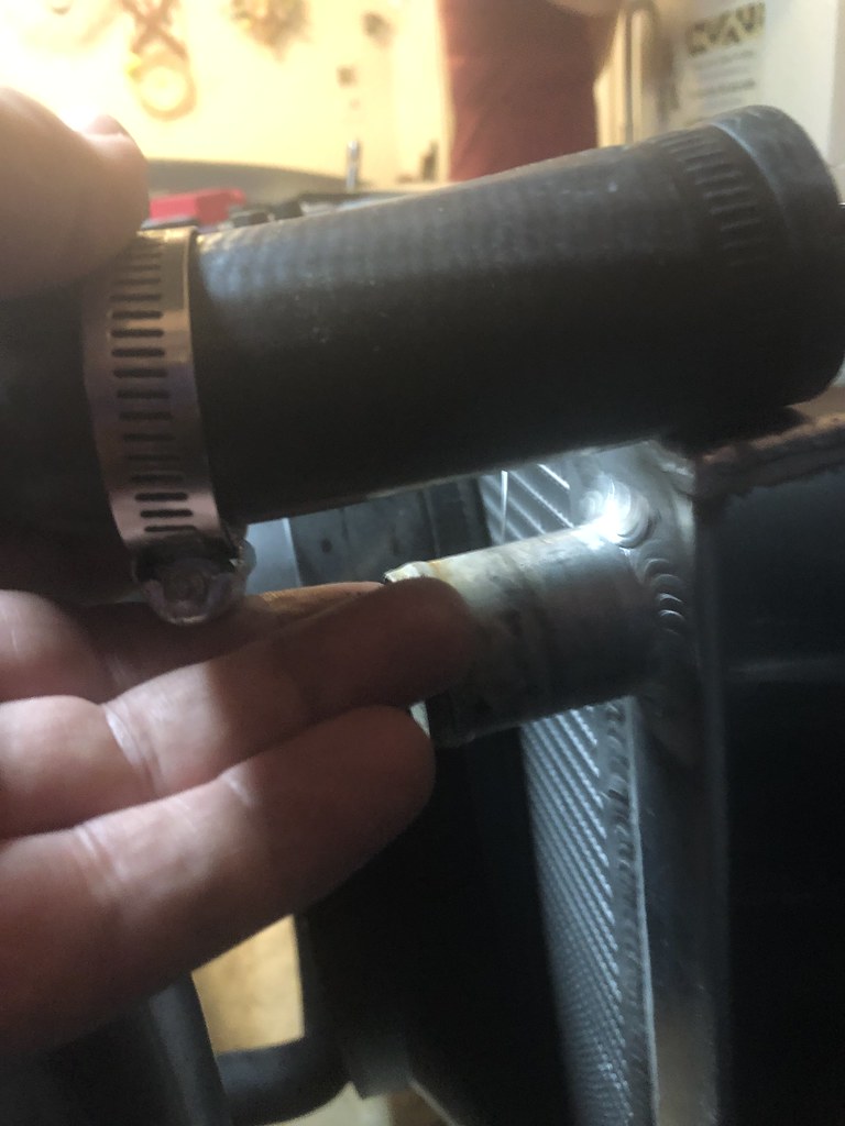

16) At this point the pipes are attached to the intercooler and loosely to the turbo. Except the size of the silicon 90 degree elbow has the pipe pointing upwards to where I was worried I’d hit it on the hood. It was as far down on the outlet as it would go, but still had a bad angle. So I had to trim the turbo side of the coupling.
Here you can see how much I had to trim.

17) Now that everything was where I wanted it I went to each clamp and tightened it. Between tightening each clamp I confirmed nothing shifted, especially around the fan.
18) Some people talk about leaving the intercooler hanging by the piping and clamps but that seems really risky, especially if you blow off a clamp with high boost. So I built some brackets to hang the intercooler from the radiator support and added some straps on the bottom.


19) now I had to trim the wheel liner to fit around the U pipes. Again I wish I’d removed the liners while doing this, but here is roughly what I had to cut.


20 ) Final step was to install the BOV and run another line to the vacuum tree on the firewall, then put the tires on.
Some pictures of the finished product.


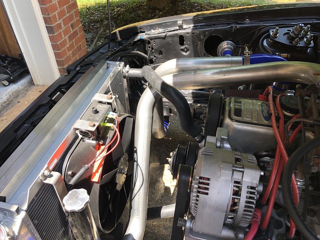
Now that I have a bigger turbo and the FMIC I’ll start tuning again and not worry about too much boost with the intercooler.
No comments:
Post a Comment